Initial Research for a Two-wheeled Robot
My initial goal was to find some other examples of two-wheeled robots. Many of these robots are ‘self-balancing’ and have their center of gravity above the pivot point of the wheels. I have built a robot like this and was not really interested in doing that again, at least for now. I am looking to make a robot that is more mobile than my previous robots and the drawback of having to balance the entire robot on two wheels does not meet that criteria. I would need to build something a little different.
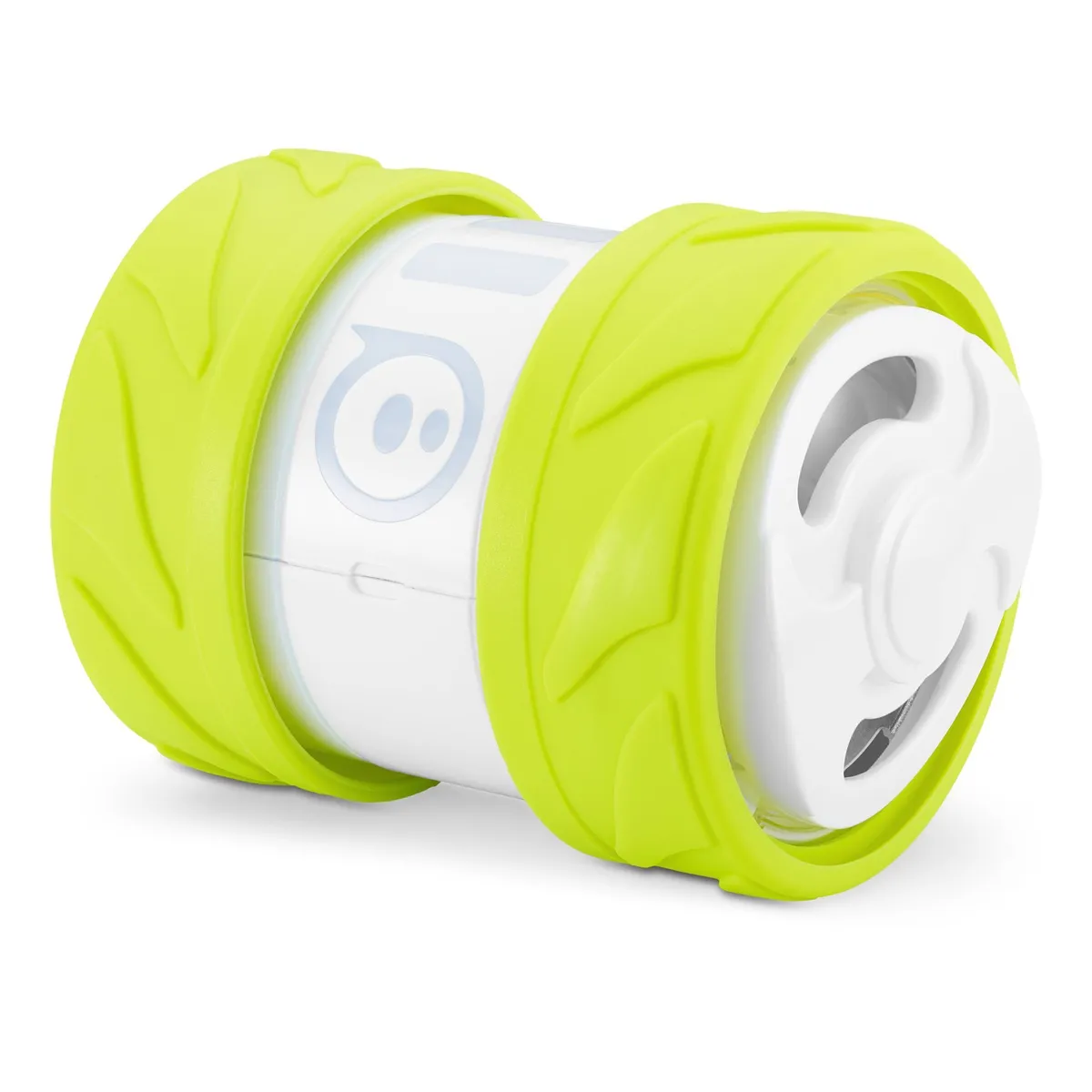
The inspiration for Goblin came from two places. The first is the Ollie robot from Sphero and the second is the CanBot from Max Kern.

Sphero Ollie product photo
I found more information on the Ollie robot from Sphero in a patent published online via the US Patent Office as SELF - PROPELLED DEVICE WITH CENTER OF MASS DRIVE SYSTEM which was helpful in the long run but confusing at the start due to the rather obtuse language. The main insight I derived from the patent was the operating principle of the robot.
From the patent US20180299879A1:
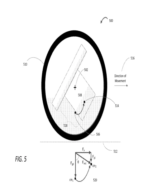
Actuation of the motors allowing for rotational pitch of the drive system may be achieved in any number of ways . For example , a mass of the wheels , tires , and hub covers collectively may be greater than a mass of the body and interior components of the self - propelled device . This causes rotation of the body and interior components initially , which in turn causes the center of mass to be displaced , allowing the self - propelled device to " fall ” towards the displaced center of mass . A weight ratio between the wheels and the interior components may be substantially equivalent , between 1 : 1 and 2 : 1 . However , any suitable weight ratio between the wheels and interior com ponents can be utilized to drive the self - propelled device in the above manner.

FIG.5 from the Sphero Ollie patent
When the drive motors begin to turn, they turn the wheels as well as tip the body due to the mass ratio between the wheels and the body. This behavior is based on the concept of rotational moment of inertia. Using wheels of lower mass and a body of higher mass means the rotational acceleration of the body is less that of the wheels. Given that wheels are what is moving the robot forward this is the best outcome. Not to mention the stability increase of reducing the tipping of the body.
As a side note: This became much more important in the second revision my robot’s design. I am writing this log based on my notes retroactively.
At this point, I know that I need a central axle for the wheels to rotate around and a way to connect the motors to the wheels, like a pulley. I think a pulley with a small belt is the best option at this scale. 3D-printing a gear box was a bit out of my wheelhouse this time around. After all, I wanted to get a proof of concept for this robot first, and having to engineer a gearbox from scratch would not make that easy.
The plan going forward is to design a two-wheeled robot with a low center of gravity. The body of the robot will be suspended between two drive assemblies, each with a pulley for moving the wheels. The body will rotate as the motors engage and a control loop will keep the pitch angle within a good range to allow for acceleration.