How I turned my 3D-printer into a 2D plotter
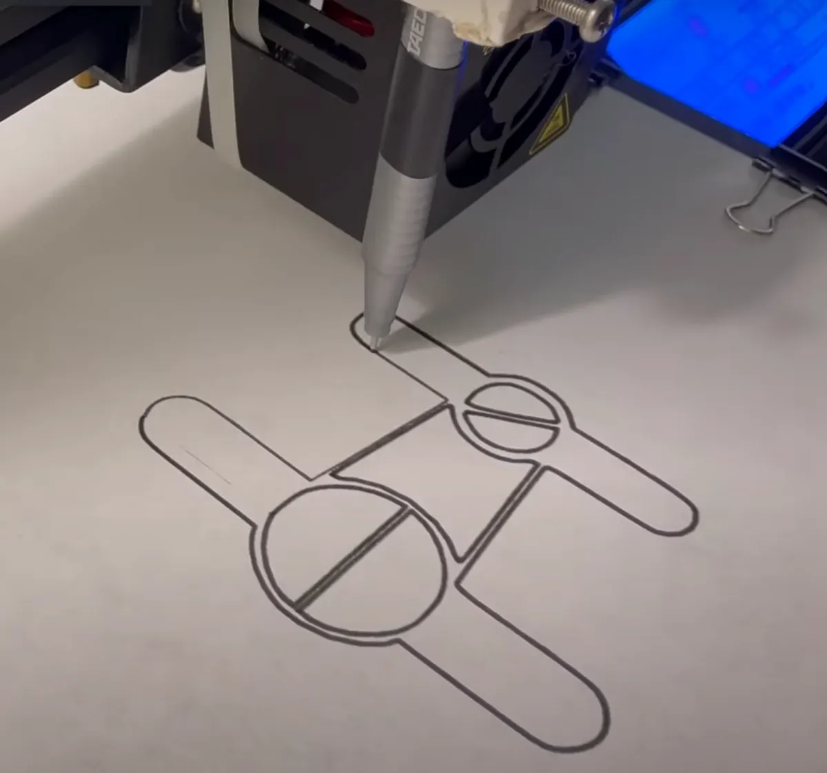
While I am home for the holidays I decided to work on a project that was small in scale but fun nevertheless. I’m going to use my Ender 3 3D printer to make a 2D pen plotter. In the end I want to have my 3D capable machine limited to two dimensions.

The only issue with this is that I still must compensate for that third dimension in the form of the Z axis offset from the print bed; more on that later. I plan on using using a 0.3 millimeter felt tip pen as the tool for drawing. I took a loose measurement of the pen’s width to start. I found a printable attachment for the Ender 3 that would allow me to modify the parameters for my pen. I used the OpenSCAD file included in the Thingiverse download to set the tool diameter to 10 millimeters. This was as simple as opening the OpenSCAD document and changing the variable that was at the top of the script for the tool diameter. This dimension turned out to be a little too large but I will deal with that later. This is a key advantage of rapid prototyping, it’s rapid!
Pen/Pencil/Marker mount for Creality Ender 3 / CR-20 by Urish (Thingiverse)
Next, I printed the attachment. After some melting with an old soldering iron I got a captive nut and an M3 screw to hold the pen in place. I used a piece of electrical tape and a strategically placed zip tie to hold the attachment to the tool head of the printer. The zip tie was sufficient for preventing the attachment from tilting forward and backward as the pen drags on the page as well as securing it downwards so it wont come off entirely. The pen was a little too loose as I mentioned before. Rather than reprinting the part, I just stuck a pen cap next to the pen as a shim for now.
In order to tell the slicer where to start the print, I had to see at what Z height the the pen tip was from the bed as well as what X and Y position it was offset from the normal extruder print head. I measure this by moving the print head, manually with the controls on the Ender 3. I measured that the pen would touch the page at around 11 millimeters above ‘normal’ printing height (where the extruder would usually touch the build-plate).
In the Cura slicing software, I changed my machine settings to turn off the heated bed and changed my nozzle size to 0.3 millimeters, the same size as my pen. The wall thickness was set 0.3 millimeters as well. I set the wall line count to 2 as I prefer the thicker outline in the final drawing. In order for the lines to stay on one level, the top to bottom thickness is set at 0 millimeters. I chose a 60 percent lines infill which depending on the size of the graphic will fill in the black areas of the design. It is an absolute necessity that the extruder does not heat up while I only want to draw so I set the material temperatures to zero.
I enabled the retraction setting so that Z-hop could be enabled. The Z-offset setting is not a part of Cura by default. I had to install a plugin from the marketplace called, ‘Z-offset setting’. This is where the 11 millimeter Z offset is entered.
For a walkthrough of these settings check out the video of this project on YouTube:
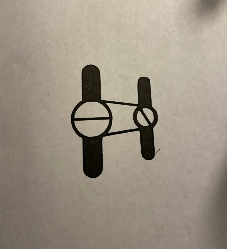
I imported an STL file that I converted from an SVG of the Hackbatch logo. I used this tool to upload my black and white vector graphic and download a 1 mm tall STL file. Once imported into Cura I used the X and Y offsets I measured earlier to shift the print so that it was aligned with where the pen would actually draw it in the center of the page. In my case this was -35 mm in the Y direction and 40 mm in the X direction.
The final step is to scale the print so that it is only one layer. I did this by turning off uniform scaling and adjusting the Z scale of the 'object' until I could slice the model and get an estimated print time. If I could not get a print preview and an estimated time, the print would fail in my testing. The final setting I used was 0.2 mm Z-scale.
